
When you start to add more and more accessories to your Tacoma, it can get a bit overwhelming with wiring. Dealing with multiple switches, fuses, and relays everywhere, really cluttering your engine bay.
The basic factory-style blanks will work, but what happens when you run out of space? On average, you’ll have about 1-3 empty locations to add your OEM-style push buttons to the factory panels on your dash. Now imagine the abundance of wires, relays, and inline fuses that are needed to run to wire up the switch for each accessory.
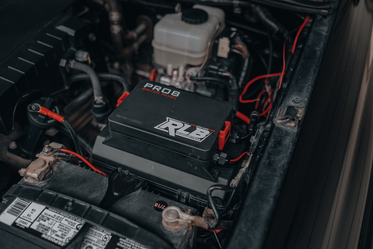
A great way to organize the messy wires and allow more switches is a panel from Rear Light Bar (RLB).
RLB has some great products that we’ve already covered, the universal rock lights and rear chase light bar.
Find It Online
- Rear Light Bar (RLB) Pro8 Switch Panel: Check Price
Table Of Contents
Power Module

The Pro8 is an 8 button programmable switch panel that can be used to power any 12v accessory for any off-road vehicle. The kit is plug-and-play, as all you need is a vehicle battery to power the module and it comes with all the necessary hardware to install.
The power module has the option to be directly wired to the battery of the vehicle or to be wired to a keyed fuse box. In the latter, the panel is only functional when the key is in the on position.
Both the power module and switch panel are waterproof as well, so no need to worry about finding a dry place to mount them either.
Key Features
- 4 Supplied Mounting Solutions
- On/Off/Memory Button
- Unique user-selectable legend
- 8 user-selectable programmable switches
- 30 amp circuits (can be swapped for other amperage fuses)
- Waterproof power module
- 100% serviceable
- 4 backlight options
- Low voltage cut-off protection
- Overvoltage protection
One standout feature is the On/Off Memory Button. Use the On/Off/Memory when shutting down or turning on multiple lights/accessories at once. The system will store in memory all the accessories that were on when shutting the system down. Then when you’re ready to go, use the On/Off/Memory button to turn the system back on. This will activate all the same items that you last shut down with 1 single button press.
Circuit Board

Inside the power module, you find the heart of the system. A completely 100% serviceable fuse and relay module. All 8 universal relays and fuses are replaceable making it easy to fix if one fails. Each circuit is rated at 30 amps but can be swapped out to one that’s needed to match your accessory power rating.
Inside is also where you will find the positive terminal to connect your accessories. Wire connectors are supplied so all you need to do is crimp them on.
Waterproof Housing

The power module is waterproof with the help of cable sheaths and waterproof plugs.
The waterproof plugs will stay in place when that accessory button isn’t needed. Otherwise, you will run the power wire through the cable sheaths.

On the other side of the module is where the positive and negative wires are located to power the module.
The waterproof control wire is also located here that will plug into the panel.
Switch Panel

The switch panel contains 8 electronic programmable buttons with the middle RLB logo being the power button. It also comes with 4 backlight color options; white, blue, green, and red, as well as being able to adjust the brightness of each. All of this can be set directly through the switch panel programming.
Each button has 6 different programmable features:
- On/off
- Momentary
- Blinker mode
- Strobe 1
- Strobe 2
- Strobe 3
Accessories

Included with the Pro8 will be a legend to customize how you please. It also comes with 4 optional mounting solutions; dash mount, flush-mount, flat surface mount, and tube clamp mount.
Each mount does require drilling except for the tube clamp mount. But of course, you can always customize a way to mount the panel without drilling. A template is also included if you choose to flush mount the panel.

The ram mount ball really helps make mounting simple when you are running some type of dash accessory kit.
Otherwise, the ram mount ball can be removed for a more flush mount type.
Installation

The Pro8 install can be done with a basic tool kit and a wire crimper.
Depending on where you mount the module and switch panel, you really only need a wrench to remove the battery terminals and crimper for wiring. Since the Pro8 is universal, you can pick a location for both the power module and switch panel that best suits your needs.
Step 1. Disconnect Negative

When installing any type of wiring, it’s always best to remove the negative battery terminal.
Step 2. Mount Module
I found it easier to first find the locations to mount both the module and switch panel.
This makes it easier to know how long and where to run your accessory wires to. I located the module on top of the fuse box and then used an existing ram mount I had to mount it.

Once you mount the module and switch panel, you can run the cable through the firewall and plug it into the module and twist tight the cables.
Step 3. Power Module

I decided to power the module by connecting directly to the battery. This gives me the capability to use the switch panel without a key in the on position.
To do this, you will connect the big positive cable with an inline fuse to the positive terminal of the battery. This will be a single wire only.

On the other side of the module, you’ll have a pair of black and red wires.
You will need to connect the black wire ONLY to the negative terminal of the battery. The red wire will be used if you are wanting to power the module to a key on the fuse box by using the provide fuse tap.
Wiring Diagram

But if you’re still confused, RLB has a diagram that is provided in the box as well.
Step 4. Wire Accessories & Auxiliary

Before completing this step, you will either need to make your own wire harness or use the existing wiring from your accessory.
Once done, you will loosen the cable gland nut from the module. Remove as many waterproof plugs as needed and run the positive wire through the cable interface. Keep the plugs in any unused spots as this is what helps aid from water getting in. When you remove the waterproof plugs, you can tighten the nut back on the cable interface.

Once you run the wire through the gland, you can now crimp the wire connector to the end of the wire.

You will then loosen and install the wire connector to the appropriate terminal. Once installed, tighten the screw until the terminal is snug.
Finally, you will need to find a location to ground the ground wire on your accessory wire harness. This can be grounded anywhere on the body or frame as long as it’s metal-to-metal contact.
Final Thoughts

The Pro8 is a really good solution to making your wiring more organized for current and future accessories. It’s affordable and really universal for any application.
I plan to organize the wiring even more by installing some sort of wire fuse box tray for the engine bay and mount it to a more flush location.
You don’t have to have 8 accessories to use this panel, but it sure does make you want to add more!
Thanks so much for this detailed description of the pro 8 and installation process…. I have a question regarding the ground wires….there is a 1-8 terminal strip covered by a plastic flip lid on the exterior of the module. It’s not shown in the wiring diagram pictured in the box and I am curious if it is a ground terminal? Any thoughts would be greatly appreciated
I’m getting power to the switch pannel but not to any of my accessories?
This has been incredibly helpful! Thank you!
Will there be a video to see all the functions the switch panel has ?
We can get one uploaded here in the future Jaymerson. But, if you like to see it sooner, send me a DM on Instagram!