

We finally wrapped up one of the most time-intensive long travel kits on the market. We linked up with Stellar Built out of Sacramento California in order to install this JD Fabrication 2.25″ long travel kit.
We already published the first post on rebuilding the outer joints on the 934 CV axles. If you miss that go check it out, it’s a pretty good post. After that, we drafted the full overview and initial thoughts on the actual long travel kit itself. This post, however, is going to cover everything that you need to know for the JD Fabrication LT installation. For this installation, you will need a couple of days and an experienced welder along with many other tools at your disposal. This install took lots of preparation, cutting, grinding, sanding, and cleaning before actually welding began.
I was able to spend the majority of time installing this kit next to Adam (@Adam_Arcs) down at Stellar Built. I was Adam’s fab assistant for everything prep; sanding, grinding, cleaning, measuring, lifting lower control arms into place, holding shocks in place, assembling parts, rebuilding CV Axles, and more.
We also relocated our body mounts during this install so that added to the steps we needed to take for prep. On top of relocating our body mounts, we pulled our factory CV axles, and steering rack and then swapped in a 200 Series Land Cruiser steering rack. I should have a full overview post for the land cruiser rack, steering clevis, and outer/inner rod ends with the Kartek tie rods coming out soon. In any case, there were quite a few steps for this installation.
JD Fabrication offers a wide range of parts you can configure your kit with. You can buy the kit in pieces & piece together your own selection of parts or buy it as a whole kit.
YotaMafia.com offers a simple product page that offers shocks (coilover & secondary) along with everything else you need for a full kit. The 934 CV axles are hard to come by right now and may be out of stock, so in that case, the RCV +2″ axles will work with this kit. As long as you are purchasing everything through YM, they will ensure you get the right components for the kit.
Let’s jump into this install.
2nd Gen Tacoma (2005-2015)
- 2005-2015 Lower Arm Pivots $100 Off (Coupon code “trailtaco”)
- 2.25″ Long Travel Kit
- Front Skid Plate
- 934 CV Axle Upgrade Kit
- Spindle Gussets
- UCA Double Shear Kit
- Secondary Bypass Mounts
- Bump Stop Kit
- FOX 8″ Coilovers
- FOX 8″ Triple Bypass Shocks
3rd Gen Tacoma (2016-Current)
- 2016-Current Lower Arm Pivots $100 Off (Coupon code “trailtaco”)
- 2.25″ Long Travel Kit
- Front Skid Plate
- 934 CV Axle Upgrade Kit
- Spindle Gussets
- UCA Double Shear Kit
- Secondary Bypass Mounts
- Bump Stop Kit
- FOX 8″ Coilovers
- FOX 8″ Triple Bypass Shocks
This kit is compatible with mid-travel shocks. You can run your current mid-travel or extended travel shocks with this LT kit; Icons, Kings, Fox, Elka, BP-51s, etc.
Table Of Contents
Installation Overview

This guide is to be used as a basic outline for installing your long travel kit. Please note that the tools we use for the installation are what’s recommended to make your life easier however you may improvise depending on the tools you have available.
Tools & Materials
- Metric/standard toolset
- Floor jack
- Jack stands
- Plasma cutter (optional)
- Grinder with cutting wheel and pad discs
- Pneumatic belt sander, barrel sander, or wire wheel cup brush bits
- 3 1/8” hole saw & drill
- Welding is required
- Painters tape
- Zip ties
- Prepping/finishing paint or STEEL-IT
Once you have the truck in the desired location get it up on jack stands and remove the front tires. The best position for the jack stands is just behind the cab mounts as this gives you ample room to work on the front end. Once the truck is up on the stands completely disassemble the front end.
Leave the brake caliper attached to the lines and hang the caliper off of the cab mount with some zip ties. You do not need to remove the axles or inner tie rods to complete the installation however doing so will make the job easier. If you do not remove the axle/tie rods make sure you cover the boots so they do not get damaged when cutting and welding. Thin sheet metal works well as a boot guard. We removed our axles, and steering rack for this install because new parts were going in so while the parts were out, we installed the long travel components.
1. Prep LCA Pivot Kit

Time to start cutting off the factory lower control arm mounts. If you have a plasma cutter this will make quick work of the job otherwise a cutting wheel will work just fine.
It’s important to note that the factory frames are very thin so take your time when cutting the factory mounts off. It is also important to completely sand the frame smooth so the new LCA pivots will slide into place.
This is the most time-consuming part of the job so be patient.

If you’re keeping your factory bump stops, you will need to notch the factory bump stop mounts. The reason for the notch is so the new LCA mounts can slide up into place. You want to make sure you do not cut out too much material as you will be welding the new LCA mount to the underside of the bump stop mount. If you remove too much material you will have large gaps to weld which is not ideal. We’re not using our factory bump stop mounts so we cut them off.
2. Fitting LCA Pivot Kit

This is the biggest reason why this kit stands out. The LCA pivot kit is what pushes our caster so far forward allowing us to easily… well somewhat easily run 37″ tires.
Let’s start fitting the LCA pivots to the frame.
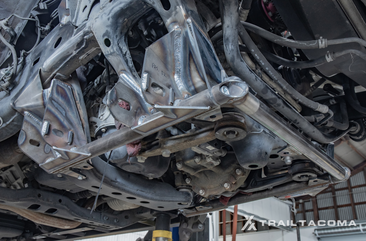
We’re using a lift but if you’re on the floor, placing a floor jack under the connecting tube on the LCA mount will also be a big help in getting it up into position. I would encourage anyone on the ground to assemble the cradle and the crossbar together and then jack those up into place together, then bolting them on for welding.

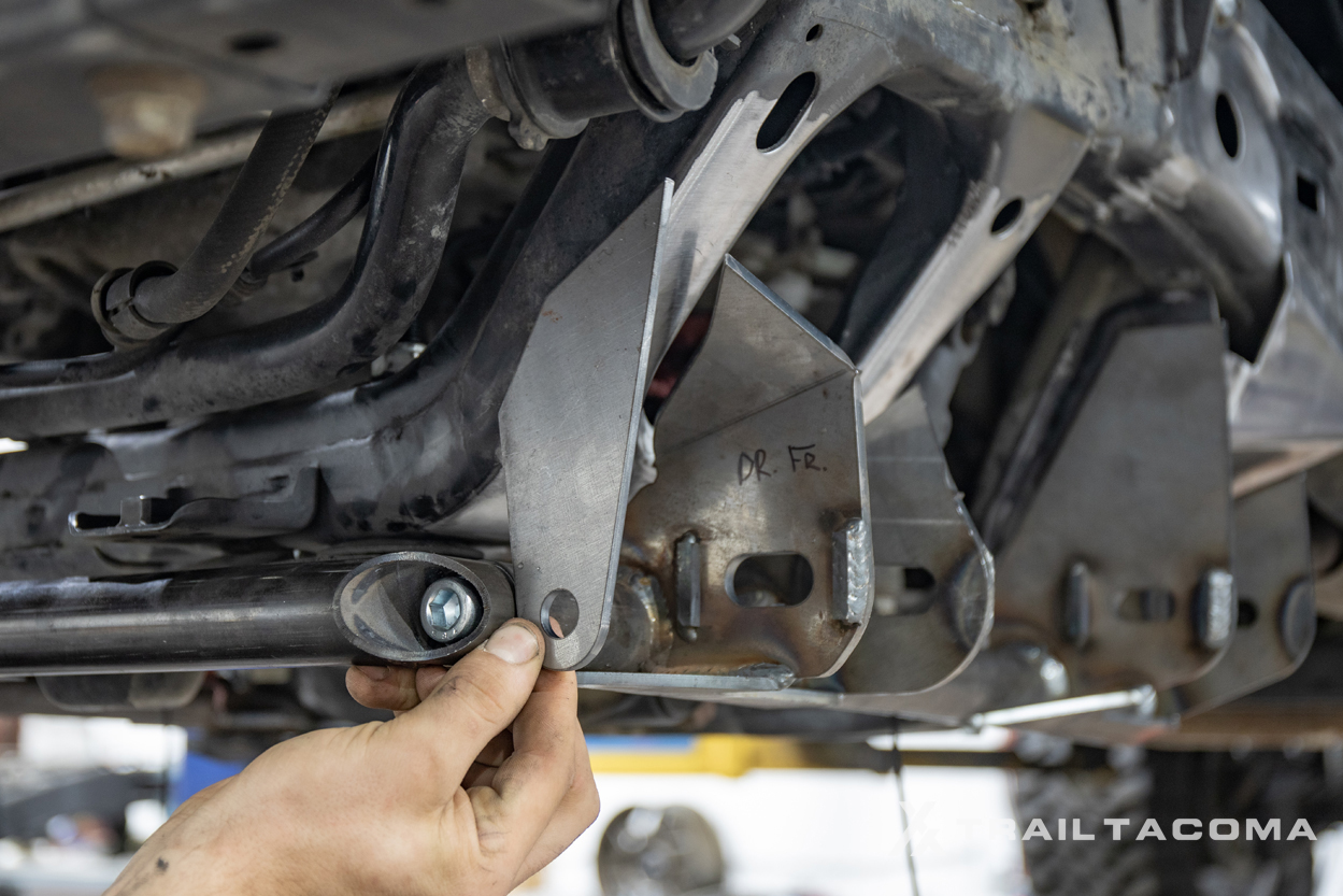
The LCA kit is designed with locating tabs (seen above with red arrows) at the rear of the pivots to ensure the kit is aligned properly to the factory frame. Start by sliding the new LCA mount into position and use the supplied 8mm bolts to secure the LCA pivots to the frame.
3. Position LCA Pivot Kit

Every truck is a little different and how the truck was used prior to the installation will be the biggest variable. Trucks that have seen heavy off-road abuse will most likely have bent frames to some degree. When positioning the LCA cradle it’s important to make sure the new tabs fit snug up against the factory frame. To ensure proper welding, and In the case that the frame has some bending it may be necessary to grind some material out on the new LCA tabs. Once the kit is fitted to the frame mark areas where some grinding is necessary and slowly remove material from the tabs until the entire LCA kit fits snugly against the frame. 1/8″ gaps are acceptable and easily achievable on even the most used and abused frames. Our frame was pretty straight, we didn’t need to take any material out.
4. Tack Weld LCA Pivot Kit

Heat setting: 18volts (Adjust accordingly)
Once the LCA kit is fitted to the frame properly and the locating bolts are tightened up, start by tack welding all the tabs to the frame. When welding the new tabs to the frame it’s important to move the heat around initially so the LCA mounts do not get pulled out of position.
Again the factory frame is thin and the correct way to weld the tabs to the frame is by putting the majority of the heat into the new tabs and then whip the puddle into the factory frame. A heat setting of 18volts is a good starting place however you can adjust accordingly depending on your welder.
5. Weld Rear Tabs

Make sure you do not weld the middle section of the rear tab so the cam has its adjustment range.
6. Weld in 1/8″ frame fill plates
Once the LCA pivots are fully welded to the factory frame, install the supplied 1/8″ frame fill plates. This is done by sliding the plates in from the backside of the LCA mount.

The most rearward tab on the LCA kit is notched out so the plate will slip in from the backside. Once you slide the fill plates in fully weld everything up.
7. Finish Welding Pivot Kit
After you’re finished, do one final check to make sure you’ve made contact with all available tab points on the frame.
8. Prep Upper Control Arm Double Shear

In the UCA double shear kit, you’re provided with three brackets. The larger plate is positioned on the forward most point of the vehicle and the two smaller plates are positioned towards the rear of the vehicle.
9. Position and Test Fit UCA

Before welding any plates to the frame rail, slide in the UCA long bolt and UCAs in order to finalize fitment.
10. Weld UCA Double Shear Plates

Once you have verified the correct orientation of the plates and are comfortable with the location of the upper control arm, continue tack welding the plates and then finally weld the remaining portions.
11. Notch Coilover Bucket for UCAs

Once the spindle is bolted to the lower control arm install the axles and then install the upper control arm. When the suspension is dropped out, the upper control arm will come in contact with the lip on the side of the factory coil bucket. This lip will have to be ground down in order for the suspension to completely drop out. The best way to do this is to mark where the upper control arm comes into contact with the coil bucket and sand off the lip.
12. Prep Upper Shock Mount Template

The upper mounts need to be opened up to 3 1/8” in order to clear the new upper shock mounts. JD Fabrication provides you with a hole saw alignment template to aid in the process.
13. Open Upper Shock Mount

The easiest way to do this is with a 3 1/8” hole saw. Simply bolt the template to the top side of the shock mount and start cutting the hole from the underside until you are through the factory mount. Repeat the same process for both sides.
14. Clean Coil Bucket for Shock Mount

After you have opened both factory upper mounts we recommend cleaning up the 3 1/8” holes with a barrel sander as the hole saw will leave some sharp edges. If you do not have a barrel sander a combination of a round file and a grinder with a sanding disk can achieve the same results.
15. Installing The Shocks

Once the upper shock mounts have been prepped you will need to install the upper top hat on the shock. The top hat must be bolted to the shock before it’s installed on the truck.
When installing the shock on the truck the rear top hat bolt can be a little tricky and we recommend taping the nut into a socket with a long extension to get it started. When the upper shocks are bolted in, you can then install the lower control arms and bolt the lower shock ends on.
16. Install The Lower Control Arms

Now install your LCAs. Depending on how much caster you’re looking to achieve, place the desired amount of pucks behind at the rear-most position of the Tacoma (seen above). We positioned every puck towards the rear of the Tacoma in prep for our 37″s Mickey Thompsons. Then place the provided LCA spacers on each side of the misalignments.
17. Position The Cam Tabs

Here is a closer look at the cam tabs, pucks, and spacers. If you want less caster, just position one or two pucks in front of the LCA spacer towards the front of the Tacoma. Since we plan on running 37″ tires, we want the most possible caster the kit will provide. If you’re running 35″ tires, two pucks in the rear and one in the front would be plenty. 34″ and 33″ tires go with one puck in the rear and two in the front.
18. Position Cam Tab Set Bolt

Make sure your cams are installed as seen in the picture. If it is installed the other way you will NOT be able to match drill the cam and lock out your alignment.
19. Remove Lower Ball Joint Adapters

Now you will need to prep the lower ball joint adapters so the spindle can be installed to the LCAs. We recommend cutting off the steering stops completely (pictured right-hand image above). The factory ball joint adapters are bolted to the spindle using the supplied hardware and necessary spacers. It is extremely important to Loctite these bolts in and torque them to 95ft/lbs.
20. Paint and Prep Ball Joint Adapters

We decided to paint our LCA ball joint adapters with STEEL-IT to match the rest of the components being welded to the frame. Feel free to use whatever you want. Clean and prep accordingly.
21. Install Lower Ball Joint Adapters

Position the bolts and spacers in place through the lower control arm ball joint adapters.
22. Install Spindle to A-arms

Connect the spindle to your A-arms. Now articulate suspension components without coilovers assembled in order to see its full range of up and down travel. At this time you can notch any portion of the Coilover bucket if the upper control arms make contact. At this time you can also throw on a tire and articulate your full range of motion; full bump and bottom out. This will give you an idea of what and where you will need to cut to clear larger tires.
24. Test Fit Bump Stops Cans and LCA Contact Points

Test fit the hydraulic bump stops, cans, and plates while compressing the suspension to bottom out on the coilovers. Find the strike plate on the lower control arms. At full compression, match the bump stop head with the strike plate on the lower control arms. Mark plate locations and then correct the bolt orientation on the cans so that they do not collide with secondary bypass shocks.
25. Notch Coil Tower for Bump Stop Plate

Depending on bump stop placement, you may need to notch the coilover bucket in order to position the plate flush up against the bucket for welding. Cut and clean this area before welding.
26. Tack Weld Brackets to Cans

Prep the cans and brackets on a table before positioning them before final welding.
27. Weld Cans & Brackets
Finally, weld the cans and brackets in place.
28. Prep Limit Straps

Masking tape off the limit straps material so that no burning metal or sparks hit the material directly.
29. Test-Fit Travel for Limit Straps

When installing the limit straps start with the chip in the lower position. With the suspension at bottom out, measure 1” down on the shock shaft and mark a line on the shaft. Then compress the suspension back up to that mark and tack the limit strap tab to the frame. Make sure when the suspension is dropped out that the limit strap stops the suspension before the upper ball joint makes metal-on-metal contact. If need be the chip in the tab can be flipped thus shortening the limit strap length before or after welding.
We ended up having to flip ours after the install because fully drooped out, the UCAs made contact on the spring on our coilovers. Flipping the chip in the limit strap lost us a little down travel but will save our springs from getting destroyed over time.
30. Weld Limit Straps Tabs

Once you have confirmed your limit strap bracket placement, weld it in.
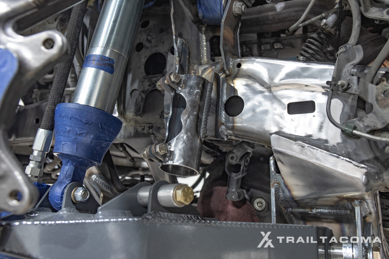
31. Test-Fit Reservoirs

For the remote reservoirs on the coilovers, position the reservoir and then tack weld the reservoir mounts to the side of the frame.
Now, this is where things get interesting. Clearance with 35″ tires was fine. But, after we mounted our 37″ tires, we started rubbing on the reservoirs in the front and the rear. If you plan on running 37″ tires with this kit, I would suggest mounting the front reservoir on top of the frame rail completely free from a full tire turning radius. You might need to notch the UCA gusset in order for the reservoir hose to clear. This is one area you want to really think about if you plan for larger tires.
32. Weld in Reservoir Brackets

Tack weld in the reservoir brackets first and test-fit the reservoir. Once the reservoir has the correct position and sits parallel to the frame rail, weld the remaining portion.
33. Test-fit Secondary Shock Hoops

If you purchased a secondary shock mount for your kit, you can install it towards the end of your installation. After you have opened up the upper shock mounts, bolt the bypass mounts on. To get the bypass mounts to sit flush against the frame you will have to sand down some exposed bolts that protrude through the inner fenders.
34. Tack-Weld Frame Rail Hoop Plates

Once the bypass mounts are bolted up mark where they land on the side of the frame, then remove the bypass mounts and weld the supplied square plates on the frame with them centered over the marked hole.
35. Weld in Hoop Mount & Filler Plates

Once the frame plates are welded reinstall the bypass mounts and weld them to the square plate. Then fit the supplied gussets in and weld them up. It’s recommended that you paint the backside of the bypass mounts before they are welded on as you will not be able to once they are installed.
For the rear reservoirs, we installed those on the actual hoops. If you plan on running 37″ or larger tires, you will rub on the reservoirs here. I would suggest installing the reservoirs as high as you can, up into the inner fender area, or even inside the engine bay if you are running open fenders. Right now, we’re running our inner fenders but we plan on installing the JD Fabrication inner fender kit. With that kit in place, that should allow us to mount our reservoirs even higher and more tucked away from our turning radius.
Extra
Brake Lines
Don’t forget to install the supplied brake lines and we recommend zip tying the ABS lines to the brake lines. We also supply you with adele clamps that allow you to bolt the brake like to the factory bolt hole in the spindle.
Finish Paint
It’s recommended that you finish painting all your bare metal before installing your shocks. We used black STEEL-IT to get a really thick paint coating along the frame rail but you can use your undercoating paint of choice.
Final Thoughts

How was this kit off-road? We still have quite a bit of work to do before it’s fully dialed. With the 35″ tires, the kit did great both on-road and off-road. We should have left well enough alone and stayed on 35″ tires. But where is the fun in that? We of course had to our push our limits for you guys in order to really see what’s possible with this kit.
To start, we need to relocate both of our reservoirs because the 37″ tires are rubbing. Again, if you run this setup with 35″ tires, you will be fine. We also need to tune each shock, both the coilovers and the secondary bypass shocks. Eventually, we’re going back in for our inner fender kit and an upgraded steering pump to better assist our 200 series land cruiser rack and 37″ tires.
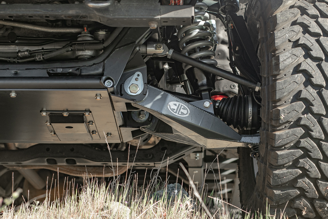
All that said, this kit is unbelievable. The LCA pivot kit is a true game-changer in the way it pushes the caster so far forward. If you’re really looking to push your wheel/tire away from the firewall, this kit will do it. After years of beating on multiple trucks’ firewalls and pinch seams, I will never look back. The JD Fabrication kit really allows you to keep your factory firewall in place while easily running a 35″ tire. No tubbing, no rubbing. It’s just flat out easy. There is unreal clearance with 1″ of caster and a full-size 35X12.5 tire. I have never seen anything like it. Even with the 37″ tire, there is still a massive 5-6″ of clearance from the lugs of a gnarly M/T to the pinch seam on the firewall. There are many long travel kits out there but none quite like this one. Forget long travel for a second, there is literally no other product like this LCA pivot kit on the market. This is the answer to almost everyone’s problem. From guys running a 33″ tire all the way up to a 37″ tire, this LCA pivot kit is it.
Off the rack, and straight to the trail, the kit killed it. We hit some mild offroad trails out here in Nothern California and the kit performed flawlessly. No problems, no knocking, no clunking, zero issues.
Game = Changed. At the minimum, go buy an LCA pivot and be prepared to be amazing. You don’t need every part on this page to have a good time but if you want to reduce your rubbing all the way around, the LCA pivot kit will change your life.
If you have any questions, let me know.

What offset wheel did you go with for this build? Any other issues with running 37’s since this article?
Probably the best article written about such a complex install. Welder settings made my heart full.
Great build and thread!
Have you had any tierod rub on the coil springs with all 3 pucks pushing the lower arm forward?
No rub on the springs, no. We have had some tire rub on the bypass shocks and both reservoirs mounted on the frame. We need to relocate those. We’ve also had a bit of rubbing on the lower shock eyelet from the caliper bolt. We’ve since welded on some steer stops and the rubbing has stopped all the way around. I think JD Fab is now including steer stops on all their lowers.
Well done on the installation portion of this kit. Nice to have this level of documentation when heading into a shop. I reached out to YM and they’re not currently selling the 934s, they’re also incredibly expensive. In your honest opinion, would you feel comfortable running the RCV 2″ axles you mentioned or would you 100% try to go with the 934s? Also, what are your thoughts on the land cruiser rack vs factory rack. Planning on 35″ tires, I just want to stay on the factory rack and maybe go with RCVs instead of the 934s from JD. I… Read more »
You definitely don’t “need” the 934 axles for this kit. Don’t get me wrong, they’re incredibly stout, however, they are designed for extreme abuse, whether that’s in the rocks or going fast. If you want the most accurate information about your specific set-up, I would reach out to JD Fabrication directly and talk to them about the 934s vs. other axles on the market. And just because YM doesn’t sell them, doesn’t mean JD does not. JD might build you a set of 934s with the inners and outers with your core so you don’t have to spend time rebuilding… Read more »
Bro….This is an encyclopedia for LT Tacomas!! Konrad, you taking notes? ;P
Dang dude! This post slaps so hard. Just as hard as this kit. Nice work… Can’t wait to see what else this little truck is capable of.